# Introduction
Students will be presented with an overview of how we can read output from sensors.
# Review: Arduino IDE
Goal: install (if applicable) and test the Arduino IDE with the Uno board on your laptop or desktop computer.
For your reference:
# Exercise 1: Blink
- Download and install the Arduino IDE for your operating system if you are using your own machine.
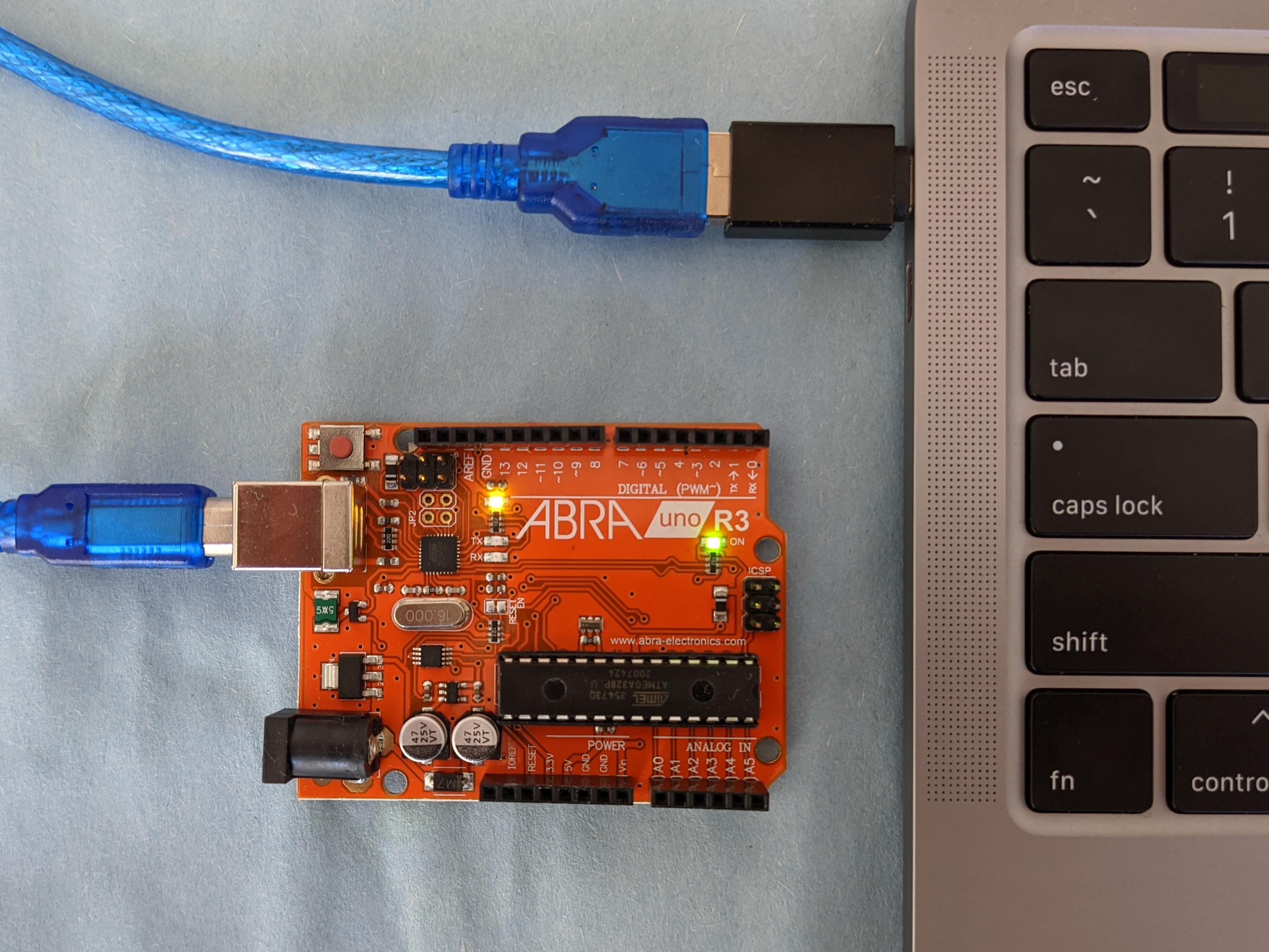
- Connect your laptop or desktop to the Uno via USB. To upload and run sketches your computer needs to know which board you are using and which port will be used for communication. From the dropdown menu select the correct board: Tools/Board/Arduino Uno. From the dropdown menu select the correct port which will differ from machine to machine: Tools/Port/"/dev/cu.name". A default "Blink" sketch may already loaded on the board.
Which port?
To know which port, you can look at which ports are available with your Uno disconnected. A new port will appear when you reconnect your board.
Open the "Blink" example in the IDE, from the dropdown menu: File/Examples/01.Basics. Change the 1000 millisecond delay to
delay(2000). Try to compile the program using the check mark icon. Upload to your board and run using the right arrow icon.If you have uploaded successfully the Uno board builtin LED near the GND and digital 13 pins will blink on and off with each state lasting two seconds.
Play around with different timing delays to see how you can control the built-in LED.
# Exercise 2: Ultrasonic Sensor
The main goals of this exercise are to understand how to use the serial monitor in the Arduino IDE and confirm that an ultrasonic sensor works as expected.
# Task 1: Obstacle detection (virtual)
Goal: Understand obstacle detection distance with an ultrasonic sensor
Ultrasonic sensors can be used for detecting obstacles. We want to validate the HC-SR04 ultrasonic sensor to understand how it works and to output some data with it. The program (sketch) below triggers the ultrasonic pin by sending a HIGH signal for 10 microseconds and then uses pulseIn to get the time in microseconds it took for the echo received by to the sensor when an obstacle is present to reflect the signal. The program also uses the Serial to output that duration in microseconds.
Find distance
By clicking on the buttons under the robot environment, you can change the position of the robot. Find the distance of the obstacle for each position.
The time between a triggered sound wave pulse and its received echo is used to determine distance. Specifically, you can use this equation in the code:
distance= duration*0.034/2;
Can you explain why?
# Task 2: Obstacle detection (physical)
Goal: test the ultrasonic sensor using your modified code.
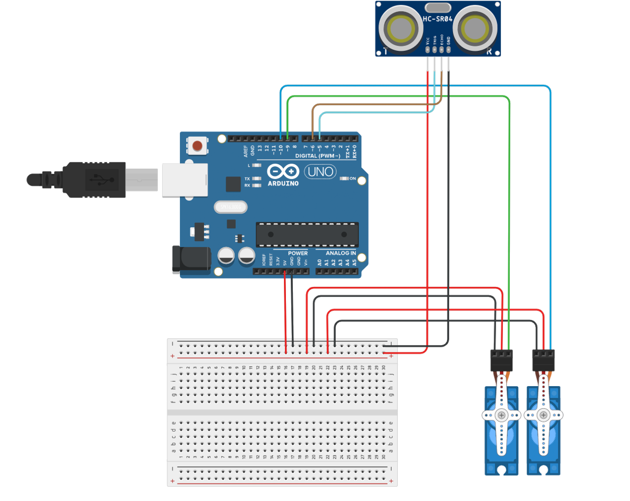
- Wire up the ultrasonic sensor [see demo, ignore servos in the diagram].
- Download the working example from task 1 (click the 3 vertical dots). Upload this to your Arduino Uno board.
- Open the serial monitor on the Arduino IDE while the program is running by clicking the magnifying glass icon on the far right of the icon ribbon. [see demo]
Serial Monitor
The Serial Monitor is a separate pop-up window that outputs serial data communicated between the Arduino and your computer. It can be useful for debugging hardware and programming logic.
- Using an object such as a notebook or piece of paper, place it at a known perpendicular distance, say 50cm. Confirm that the sensor is working properly by taking measurements. 2cm accuracy is fairly reasonable. Troubleshoot if you are not getting a reasonable result.
Ultrasonic Sensor Range
The HC-SR04 sensor provides 2cm to 400cm of non-contact measurement functionality with a ranging accuracy that can reach up to 3mm.
- Some other things to experiment with:
Place your object at different angles to the sensor to see how the reading changes;
Change your
delay()to vary how often a measurement is taken.
# About the ultrasonic sensor
If you want to learn more how the HC-SR04 ultrasonic sensor works, here are some resources:
# Exercise 3: Data Logging [see demo]
Goal: Learn how to log sensor data to an SD card and analyze it later.
In this exercise, you'll connect an SD card module to your Arduino and log distance readings from your ultrasonic sensor. This is a fundamental skill for data collection in robotics and environmental monitoring projects.
# Task 1: Hardware Setup
Connect the SD card module to your Arduino following this pin mapping:
- CS → Pin 10
- MOSI → Pin 11
- MISO → Pin 12
- SCK → Pin 13
- VCC → 5V
- GND → GND
Keep your ultrasonic sensor connected as in the previous exercise:
- Trigger → Pin 2
- Echo → Pin 3
- VCC → 5V
- GND → GND
# Task 2: Programming for Data Logging
Below is a complete working example that logs ultrasonic sensor readings to an SD card. The data will be stored in CSV format for easy analysis.
/*
  Ultrasonic Sensor Data Logger

  This sketch reads distance measurements from an HC-SR04 ultrasonic sensor
  and logs the data to a CSV file on an SD card.
*/

#include <SPI.h>
#include <SD.h>

// Ultrasonic sensor pins
const int trigPin = 2;
const int echoPin = 3;

// SD card chip select pin
const int chipSelect = 10;

// Variables for calculating distance
long duration;
float distance;

// File for data logging
File dataFile;
String fileName = "DISTANCE.CSV";

void setup() {
  // Initialize serial communication
  Serial.begin(9600);

  // Setup ultrasonic sensor pins
  pinMode(trigPin, OUTPUT);
  pinMode(echoPin, INPUT);

  // Initialize SD card
  Serial.print("Initializing SD card...");

  if (!SD.begin(chipSelect)) {
    Serial.println("SD card initialization failed!");
    // Don't proceed if SD card initialization fails
    while (1);
  }

  Serial.println("SD card initialized successfully.");

  // Create/open data file and write header
  dataFile = SD.open(fileName, FILE_WRITE);
  if (dataFile) {
    // If this is a new file, write the header
    if (dataFile.size() == 0) {
      dataFile.println("Time(ms),Distance(cm)");
    }
    dataFile.close();
    Serial.println("Data file ready.");
  } else {
    Serial.println("Error opening data file!");
  }
}

void loop() {
  // Clear the trigger pin
  digitalWrite(trigPin, LOW);
  delayMicroseconds(2);

  // Send 10μs pulse to trigger pin
  digitalWrite(trigPin, HIGH);
  delayMicroseconds(10);
  digitalWrite(trigPin, LOW);

  // Measure the response from echo pin
  duration = pulseIn(echoPin, HIGH);

  // Calculate distance in centimeters
  distance = duration * 0.034 / 2;

  // Get current time in milliseconds
  unsigned long currentTime = millis();

  // Log data to console
  Serial.print("Time: ");
  Serial.print(currentTime);
  Serial.print(" ms, Distance: ");
  Serial.print(distance);
  Serial.println(" cm");

  // Open file and log data
  dataFile = SD.open(fileName, FILE_WRITE);

  if (dataFile) {
    dataFile.print(currentTime);
    dataFile.print(",");
    dataFile.println(distance);
    dataFile.close();
  } else {
    Serial.println("Error opening data file!");
  }

  // Wait before next reading
  delay(500);
}
# Task 3: Data Analysis
- Run your Arduino with the SD card for at least 2 minutes, collecting distance measurements.
- Remove the SD card and insert it into your computer.
- Open the DISTANCE.CSV file with a spreadsheet program like Excel, Google Sheets, or a data analysis tool like Python with pandas.
- Create a simple graph of distance vs. time.
- Try moving an object back and forth in front of the sensor and observe the resulting patterns in your graph.
# Task 4: Experiment with Modifications
Try these modifications to enhance your data logger:
- Add a button that starts and stops logging
- Include a timestamp with date and time (requires an RTC module)
- Create a new file each time the Arduino starts up
- Log multiple sensor readings in one file
- Optimize the code to reduce power consumption for field deployments
Here are some links we will be using to begin our exploration of data logging:
- Template Arduino sketch for the Ultrasonic Sensor HC-SR04 with SD logger
- Complete working data logger sketch: Ultrasonic Data Logger
- Slides on Output for Arduino